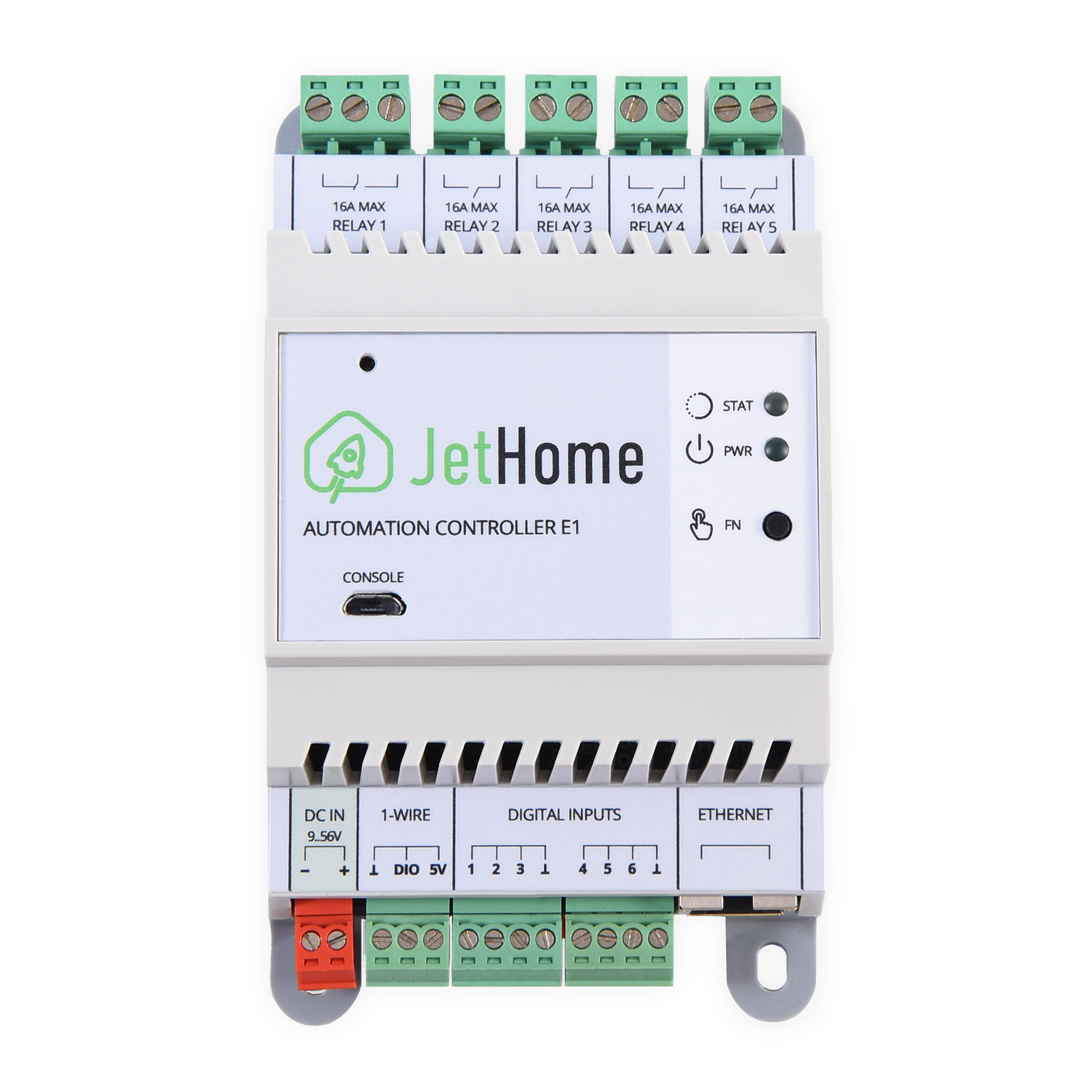
JetHub E1-PD76-R5-DC microcontroller (v2,v3)
Hint
The controller can be purchased from the manufacturer’s website: http://jethome.ru/e1/
General Description
The JetHub E1-PD76-R5-DC (v2,v3) controller is designed for controlling power loads in home automation systems. It contains five power relays, six digital dry contact inputs and a 1-Wire sensor input.
The functionality of the controller depends entirely on the software (firmware) installed by the user.
The DIN-rail enclosure design allows the controller to be conveniently placed in the electrical panel of the house.
Features
Microcontroller ESP32-D0WDQ6.
The microcontroller frequency is up to 240MHz.
SPI flash of 4 MBytes.
Built-in RAM of 520 KBytes.
Design
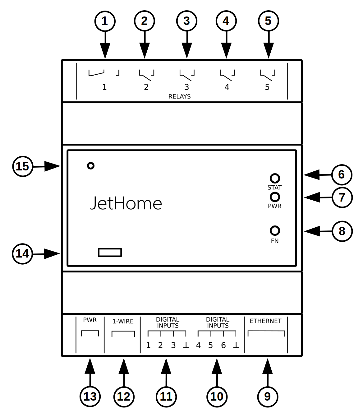
On the top side of the controller are:
Toggle relay terminal 1
Relay terminal 2
Relay terminal 3
Relay terminal 4
Relay terminal 5
On the front side of the controller there are indication and control elements:
Dual-color custom LED (STAT)
Power supply indication LED (PWR)
User button
On the underside of the controller are:
Ethernet RJ45 connector
Discrete input terminal 4-5
Discrete inputs terminal 1-3
1-Wire terminal
12-48V DC power terminal
On the front panel of the controller there are also:
MicroUSB connector
Internal hardware reset button (RESET)
Dimensions and weight
Enclosure dimensions: 130 x 76 x 57 mm.
Enclosure width is 76mm, which is about 4.3 standard modules for a DIN rail (17.5mm).
Ability to mount the enclosure to a DIN rail 35mm.
Weight: 250 g
Revisions
The JetHub E1-PD76-R5-DC (v2) controller is equipped with an E1-CPU revision 1.2 and a PD76-R5 revision 2.0 peripheral board.
The JetHub E1-PD76-R5-DC (v3) controller is equipped with an E1-CPU revision 1.3 and a PD76-R5 peripheral board revision 3.0.
Note
The JetHub E1-PD76-R5-DC (v2) and JetHub E1-PD76-R5-DC (v3) controllers are functionally identical.
However, please note that software for JetHub E1-PD76-R5-DC (v2) controllers will not work on JetHub E1-PD76-R5-DC (v3) controllers due to the different port expander chips installed in versions 2 and 3 of these controllers.
For an example, see the ESPHome configuration description under “Software “ for these controllers.
Processor module revisions
v1.3
PCA9535 port expander chip is installed instead of PCF8575.
v1.2
Added possibility to reset controller hardware through internal processor module button (accessible through a hole in the housing)
v1.1
Initial Version
Motherboard revisions
v3.0
PCA9535 port expander chip is installed instead of PCF8575.
v2.0
Added terminal for connection of 1-Wire sensors. Two versions: DC and AC power supply.
Interfaces
Wi-Fi/Bluetooth
Wi-Fi 802.11b/g/n (2.4 GHz() up to *150 Mbps.
Bluetooth v4.2 BR/EDR with support for BLE specification.
Ethernet
The built-in ESP32 IEEE-802.3-compliant MAC microcontroller is used.
The chip used as the Ethernet PHY is LAN8720A connected via the RMII interface.
Main characteristics PHY
The processor module has a PHY connection option without using an additional quartz resonator or oscillator.
The clock pulses with a frequency of 50 MHz are generated by the ESP32 microcontroller itself.
Wiring diagram
The Ethernet PHY chip is connected to the following pins of the ESP32 microcontroller:
ESP32 output |
Function |
|---|---|
IO25 |
ETH_RXD0 |
IO26 |
ETH_RXD1 |
IO27 |
ETH_CRS_DV |
IO19 |
ETH_TXD0 |
IO22 |
ETH_TXD1 |
IO21 |
ETH_TXDEN |
IO23 |
ETH_MDC |
IO18 |
ETH_MDIO |
IO17 |
50MHZ CLK OUT |
External periphery
Relay
The controller contains 5 relays with the following characteristics:
Maximum switchable current - 16A
Maximum switched - 250V AC.
Galvanic isolation between relay contacts - 1000V.
Warning
The relays are not protected against overloading and overheating. The relays and controller may be damaged if they are over rated.
Relay outputs:
The relay
1has the output type Changeover contact and is led to a three-pin screw terminal with pin spacing 5mmThe relays
2-5are of the output type NO contact and are terminated on two-pin screw terminals with pin spacing 5mm.
Discrete inputs
The controller contains 6 digital inputs type Dry Contact, brought out to two external four-pin screw terminals with contact spacing of 3.5mm.
The binary input must be shorted to the common contact GND.
Warning
Be careful when connecting the digital inputs. Do not allow voltage to be applied to the digital inputs, there are pull-up resistors to 5V on the board.
1-Wire
The controller has the capability to connect external sensors via the 1-Wire bus.
The 1-Wire bus is connected to the GPIO16 ESP32 microcontroller pin.
A pull-up resistor for the 1-Wire data line is installed on the board, so there’s no need to install additional external pull-up resistors.
1-Wire 3x3.5 mm connector
Pin assignment:
Number |
Destination |
Description |
|---|---|---|
1 |
+5V |
Power output +5V (for powering external devices 1-Wire) |
2 |
1-Wire Data |
1-Wire data bus |
3 |
GND |
Common 1-Wire |
The inner periphery
Real Time Clock (RTC)
The processor module has a real-time clock chip PCF8563 (or analog).
The chip is connected to the internal I2C bus of the module. The address of the chip on the I2C bus is 0x51.
To power the RTC, install a 3V battery of the CR1220 form factor.
See also
I2C bus
The I2C bus is used to connect various peripheral devices and is routed to the following pins of the microcontroller:
ESP32 output |
Destination |
|---|---|
IO4 |
I2C SCL |
IO5 |
I2C SDA |
Recommended bus frequency: 100kHz (Standard mode) or 400kHz (Fast mode). These modes are supported by most peripheral chips.
The I2C bus is also terminated on a 40-pin expansion slot and is used to connect external peripherals.
EEPROM
Processor module EEPROM
The processor module has a non-volatile EEPROM memory chip AT24C64 (or equivalent) of 64Kbit (8 KBytes).
The purpose of this memory is to store the hardware configuration of the board or the current state of the controller.
The address of the memory chip on the I2C bus is 0x54.
EEPROM of the peripheral board
A EEPROM non-volatile memory chip AT24C64 (or analog) of 64Kbit (8 KByte) is installed on the peripheral board.
The purpose of this memory is to store the hardware configuration of the peripheral board or other user data (depends on the installed software).
The address of the memory chip on the I2C bus is 0x56.
JTAG
There are pads on the processor module to connect the JTAG connector.
The JTAG connector pin assignment is standard for a ARM 10-pin connector.
Pin assignment
Below is the pin assignment of the JTAG connector of the CPU module and its connection to the debugger CJMCU-232H:
Output |
Destination |
ESP32 output |
Debugger |
|---|---|---|---|
1 |
+3.3V |
||
2 |
TMS |
IO14 |
AD3 |
3 |
GND |
||
4 |
TCK |
IO13 |
AD0 |
5 |
GND |
||
6 |
TDO |
IO15 |
AD2 |
7 |
N.C. |
||
8 |
TDI |
IO12 |
AD1 |
9 |
GND |
GND |
|
10 |
EN |
GPIO port expanders
Processor module port expander
To increase the number of GPIO ports of the processor module, the module has a GPIO port expander chip PCF8575 or PCA9535 (starting with revision 1.3 of the processor module) connected to the I2C bus.
The address on the I2C bus is 0x20.
Processor module expander ports in use
Channel |
Function |
Description |
|---|---|---|
0 |
RED_LED |
Red status LED on the controller front panel |
1 |
GREEN_LED |
Green status LED on the controller front panel |
2 |
USER_BUTTON. |
Optional internal user button for v.1 controllers |
3 |
||
4 |
||
5 |
||
6 |
||
7 |
||
8 |
GPIO5 |
Input/Output. 40-pin connector output |
9 |
GPIO6 |
Input/Output. 40-pin connector output |
10 |
GPIO7 |
Input/Output. 40-pin connector output |
11 |
GPIO8 |
Input/Output. 40-pin connector output |
12 |
GPIO9 |
Input/Output. 40-pin connector output |
13 |
GPIO10 |
Input/Output. 40-pin connector output |
14 |
GPIO11 |
Input/Output. 40-pin connector output |
15 |
LED control logic for processor module revisions 1.1 and 1.2: logic level 0 - LED on, logic level 1 - LED off. By default, the logic level 1 (LEDs off) is set on the port expander outputs after power-up.
LED control logic for processor module revision 1.3: logic level 0 - LED off, logic level 1 - LED on. By default, the logic level 0 (LEDs off) is set on the port expander outputs after power-up.
The state of the optional user button for module revision 1.1 is determined by the following logic levels at the port expander input: 0 - button closed (pressed), 1 - button open. This button is not used in subsequent revisions of the processor module.
Peripheral board port expander
The peripheral board has a GPIO port expander chip PCF8575 or PCA9535 (starting with revision 3.0 of the peripheral board) connected to the I2C bus.
The address on the I2C bus is 0x22.
The port expander chip is used to control relays and read the status of the controller’s digital inputs.
Peripheral board expander ports in use
Channel |
Function |
Description |
|---|---|---|
0 |
INPUT 1 |
Discrete input 1 |
1 |
INPUT 2 |
Discrete input 2 |
2 |
INPUT 3 |
Discrete input 3 |
3 |
INPUT 4 |
Discrete input 4 |
4 |
INPUT 5 |
Discrete input 5 |
5 |
INPUT 6 |
Discrete input 6 |
6 |
||
7 |
||
8 |
RELAY 1 |
Relay 1 control output |
9 |
RELAY 2 |
Relay 2 control output |
10 |
RELAY 3 |
Relay control output 3 |
11 |
RELAY 4 |
Relay control output 4 |
12 |
RELAY 5 |
Relay control output 5 |
13 |
||
14 |
||
15 |
Relay control logic for peripheral board revisions up to 3.0: logic level 0 - relay on, logic level 1 - relay off. By default, after power-up the port expander outputs are set to the logic level 1 (relays are off).
Relay control logic for peripheral board revision 3.0: logic level 0 - relay off, logic level 1 - relay on. By default, after power-up the port expander outputs are set to the logic level 0 (relays are off).
The states of the digital input are determined by the following logic levels at the port expander inputs: 0 - input open, 1 - input closed.
Internal connectors
ESP32-WROOM-32 module outputs
Output |
ESP32 |
Destination |
Description |
|---|---|---|---|
1 |
GND |
General. |
|
2 |
3.3V |
Module Power. |
|
3 |
EN |
Hardware reset of the module. |
|
4 |
I36 |
GPI3 |
Interrupt input from the GPIO port expander of the CPU module. Output to the peripheral connector. |
5 |
I39 |
UART2_RX |
The RX line of the UART2 port. It is connected to the peripheral connector. |
6 |
I34 |
UART1_RX |
The RX line of the UART1 port. It is connected to the peripheral connector. |
7 |
I35 |
GPI4 |
Input. Output to the peripheral connector. |
8 |
IO32 |
GPIO1 |
Input/Output. Brought out to the peripheral connector. Reserved for CAN_TXD. |
9 |
IO33 |
UART1_TX |
TX line of the UART1 port. It is connected to the peripheral connector. |
10 |
IO25 |
ETHERNET_RXD0 |
Connecting an external Ethernet PHY. |
11 |
IO26 |
ETHERNET_RXD1 |
Connecting an external Ethernet PHY. |
12 |
IO27 |
ETHERNET_CRS_DV |
Connecting an external Ethernet PHY. |
13 |
IO14 |
SPI_CLK/JTAG_TMS |
SPI_CLK line. It is connected to the peripheral connector and the JTAG connector. |
14 |
IO12 |
SPI_MISO/JTAG_TDI |
SPI_MISO line. It is connected to the peripheral connector and the JTAG connector. |
15 |
GND |
General. |
|
16 |
IO13 |
SPI_MOSI/JTAG_TCK |
SPI_MOSI line. It is connected to the peripheral connector and the JTAG connector. |
17 |
Not used. |
||
18 |
Not used. |
||
19 |
Not used. |
||
20 |
Not used. |
||
21 |
Not used. |
||
22 |
Not used. |
||
23 |
IO15 |
GPIO2/JTAG_TDO |
I/O. Brought out to the peripheral connector and the JTAG connector. Reserved for CAN_RXD. |
24 |
IO2 |
UART2_TX |
The RX line of the UART2 port. It is connected to the peripheral connector. |
25 |
IO0 |
BUTTON |
FUNC button on the front panel of the controller. It is also used to enter firmware mode when the power is turned on. |
26 |
IO4 |
I2C_SCL |
I2C_SCL line. Terminated on the peripheral connector. |
27 |
IO16 |
GPIO0 |
Input/Output. Brought out to the peripheral connector. Reserved for SPI_CS. |
28 |
IO17 |
ETHERNET_CLK_50M |
Connecting an external Ethernet PHY. |
29 |
IO5 |
I2C_SDA |
I2C_SDA line. Terminated on the peripheral connector. |
30 |
IO18 |
ETHERNET_MDIO |
Connecting an external Ethernet PHY. |
31 |
IO19 |
ETHERNET_TXD0 |
Connecting an external Ethernet PHY. |
32 |
NC |
Not connected. |
|
33 |
IO21 |
ETHERNET_TXDEN |
Connecting an external Ethernet PHY. |
34 |
RXD0 |
UART0_RX |
UART_RX line for firmware and system message output (console). |
35 |
TXD0 |
UART0_TX |
UART_TX line for firmware and system message output (console). |
36 |
IO22 |
ETHERNET_TXD1 |
Connecting an external Ethernet PHY. |
37 |
IO23 |
ETHERNET_MDC |
Connecting an external Ethernet PHY. |
38 |
GND |
40-pin connector on the processor board
Contact |
Title |
Purpose of the E1-CPU |
|---|---|---|
1 |
+5.0V |
The processor module power supply is +5V. |
2 |
+5.0V |
The processor module power supply is +5V. |
3 |
GND |
General. |
4 |
GND |
General. |
5 |
ETH_TXN |
Connecting an external transformer to the Ethernet PHY. |
6 |
ETH_TXP |
Connecting an external transformer to the Ethernet PHY. |
7 |
ETH_RXN |
Connecting an external transformer to the Ethernet PHY. |
8 |
ETH_RXP |
Connecting an external transformer to the Ethernet PHY. |
9 |
ETH_LED1 |
Connecting an external LED to the Ethernet PHY. |
10 |
ETH_LED0 |
Connecting an external LED to the Ethernet PHY. |
11 |
GND |
General. |
12 |
SPI_MOSI |
SPI_MOSI line. Connected to pin IO13 of the ESP32. |
13 |
GPIO0 |
Input/Output. Connected to the IO16 pin of the ESP32. Reserved for SPI_CS. |
14 |
SPI_MISO |
SPI_MISO line. Connected to the IO12 pin of the ESP32. |
15 |
SPI_CLK |
SPI_CLK line. Connected to pin IO14 of the ESP32. |
16 |
GND |
General. |
17 |
I2C_SCK |
I2C_SCK line. Connected to the IO4 pin of the ESP32. |
18 |
I2C_SDA |
I2C_SDA line. Connected to the IO5 pin of the ESP32. |
19 |
GND |
General. |
20 |
UART1_RX |
UART1_RX line. Connected to the I34 pin of the ESP32 (input only). |
21 |
UART1_TX |
UART1_TX line. Connected to the IO33 pin of the ESP32. |
22 |
UART2_TX |
UART2_TX line. Connected to the IO2 pin of the ESP32. |
23 |
UART2_RX |
UART2_RX line. Connected to the I39 pin of the ESP32 (input only). |
24 |
GND |
General. |
25 |
GPIO1 |
Input/Output. Connected to the IO32 pin of the ESP32. Reserved for CAN_TX. |
26 |
GPIO2 |
Input/Output. Connected to pin IO15. Reserved for CAN_RX. |
27 |
GND |
General. |
28 |
GPIO3 |
Input. Connected to pin I36 of ESP32. Reserved for INT1 (interrupt signal from port expander). |
29 |
GPIO4 |
Input. Connected to pin I35 of ESP32. Reserved for INT2 (interrupt signal from expansion modules). |
30 |
GPIO5 |
Input/Output. Connected to GPIO port expander IO1_0 |
31 |
GPIO6 |
Input/Output. Connected to GPIO port expander IO1_1 |
32 |
GPIO7 |
Input/Output. Connected to GPIO port expander IO1_2 |
33 |
GPIO8 |
Input/Output. Connected to GPIO port expander IO1_3 |
34 |
GPIO9 |
Input/Output. Connected to GPIO port expander IO1_4 |
35 |
GPIO10 |
Input/Output. Connected to GPIO port expander IO1_5 |
36 |
GPIO11 |
Input/Output. Connected to GPIO port expander IO1_6 |
37 |
CPU_RESET |
ESP32 hardware reset. |
38 |
GND |
General. |
39 |
USB_DN |
Not used. |
40 |
USB_DP |
Not used. |
40-pin connector on the motherboard
Contact |
Title |
Purpose PD76-R5 |
|---|---|---|
1 |
+5.0V |
Processor module power supply +5V |
2 |
+5.0V |
Processor module power supply +5V |
3 |
GND |
General |
4 |
GND |
General |
5 |
ETH_TXN |
Connecting an external transformer to the Ethernet PHY |
6 |
ETH_TXP |
Connecting an external transformer to the Ethernet PHY |
7 |
ETH_RXN |
Connecting an external transformer to the Ethernet PHY |
8 |
ETH_RXP |
Connecting an external transformer to the Ethernet PHY |
9 |
ETH_LED1 |
Connecting an external LED to the Ethernet PHY |
10 |
ETH_LED0 |
Connecting an external LED to the Ethernet PHY |
11 |
GND |
General |
12 |
SPI_MOSI |
Not used |
13 |
GPIO0 |
Output to the 1-Wire DIO terminal |
14 |
SPI_MISO |
Not used |
15 |
SPI_CLK |
Not used |
16 |
GND |
General |
17 |
I2C_SCK |
Internal I2C bus |
18 |
I2C_SDA |
Internal I2C bus |
19 |
GND |
General |
20 |
UART1_RX |
Output to the internal GPIO connector - UART1 RX |
21 |
UART1_TX |
Output to the internal GPIO connector - UART1 TX |
22 |
UART2_TX |
Not used |
23 |
UART2_RX |
Not used |
24 |
GND |
General |
25 |
GPIO1 |
Output to the internal GPIO connector - GPIO1 |
26 |
GPIO2 |
Output to the internal GPIO connector - GPIO2 |
27 |
GND |
General |
28 |
GPIO3 |
Interrupt from GPIO port expander |
29 |
GPIO4 |
Not used |
30 |
GPIO5 |
Not used |
31 |
GPIO6 |
Not used |
32 |
GPIO7 |
Not used |
33 |
GPIO8 |
Not used |
34 |
GPIO9 |
Not used |
35 |
GPIO10 |
Not used |
36 |
GPIO11 |
Not used |
37 |
CPU_RESET |
Output to internal connector J3 |
38 |
GND |
General |
39 |
USB_DN |
Not used |
40 |
USB_DP |
Not used |
GPIO connector
Connector type: PLD-2x3 with 2.54 mm pitch
Contact |
Destination |
|---|---|
1 |
UART1 TX |
2 |
GPIO1 |
3 |
UART1 RX |
4 |
GPIO2 |
5 |
GND |
6 |
3.3В |
Console
The processor module board has a USB-UART interface converter on the microchip CP2102, and a MicroUSB connector on the front panel of the controller.
Power
The following power supply options are available:
From an external stabilized DC source via an external terminal.
Note
Recommended (rated) input voltage range 12V to 48V
The maximum input supply voltage range is 9 to 56V.
A stabilized DC power supply of at least 5W must be used.
Via technology Passive PoE via the Ethernet port connector.
Note
Recommended nominal input supply voltage Passive PoE - 12 to 48V
The polarity does not matter. The recommended power scheme is: “+” power supply to pins 4 and 5, “-” power supply to pins 7 and 8 of the Ethernet connector
Note
If power is applied to both the external terminal and the Ethernet connector at the same time, power will be supplied from a high voltage source. It is recommended to use one of the power supply options.
Warning
There is no galvanic isolation of the power supply circuits in the controller.
Software
See also
Officially supported software:
ESPHome - ESP32 firmware to work with Home Assistant.
ESP-IDF - official SDK from Espressif for development on ESP32.
Note
It is also possible to use any other software for ESP32: Tasmota, Arduino and others.
Controller firmware
The ESP32 microcontroller has the ability to flash over a dedicated UART0 interface (pins IO34 and IO35 of the ESP32 module).
For flashing it is enough to connect the processor module board to the computer through the USB interface, through the MicroUSB connector on the front panel of the controller.
Note
When using standard tools for flashing ESP32 microcontrollers the switch to the bootloader mode is made automatically when flashing.
Note
The processor module can be powered from the MicroUSB connector during flashing.
This will not supply power to the lower controller board.
Safety precautions
During operation and maintenance of the controller the requirements of GOST 12.3.019-80, “The rules of operation of electrical installations of consumers” and “Safety rules for the operation of electrical installations of consumers” should be observed.
Any connections to the unit and maintenance work should be performed only when the controller and the actuators connected to it are de-energized.
Only qualified service personnel should be allowed physical access to the controller during installation and maintenance.
Do not allow moisture to get on the contacts of output connectors and internal elements of the controller.
The controller must not be used in the presence of acids, alkalis, oils and other aggressive substances in the atmosphere.
The controller is not intended for use on objects that are potentially dangerous to life and health of others.
It is not allowed to connect the instrument to the local Ethernet network with access to the Internet network without providing reliable means of interconnection protection.
Mounting
The unit can be installed in an electrical equipment cabinet or other location, where it must be protected from moisture, dirt and foreign objects, as well as vibration-free.
Note
For better cooling of the internal components, the housing should be installed in an upright position.
To install it, you have to:
Make sure there is enough space to connect the device and run the wires.
Securely fasten the unit to the DIN rail or to a vertical surface with screws.
To remove it from the DIN-rail you should:
Insert the tip of a screwdriver into the latch eyelet.
Press the latch down.
Take the controller away from the DIN rail.
Operating conditions
Ambient temperature: 0..+40 С.
Relative humidity up to 80% without condensation.
Closed explosion-proof rooms without aggressive vapors and gases.
Wiring recommendations
It is recommended that stranded copper cables be used to ensure reliable electrical connections. The cable ends should be stripped and then tinned or cable lugs should be used. The cable strands should be stripped so that their bare ends do not protrude beyond the terminal block after connection to the controller.
General requirements for connection lines:
When laying the cables, the communication lines that connect the device to the sensors or other devices should be separated into separate routes, and located separately from power cables and cables that cause high-frequency and pulse interference.
To protect the inputs of the device from the influence of electromagnetic interference, the communication lines of the controller should be shielded. Special cables with braided shielding can be used as shields.
It is recommended to install line noise filters in the power line of the controller.
In the case of controlling power equipment, it is recommended that spark-quenching filters be installed on the switching line of this equipment.
Limitations
Warning
The device is not intended for use in facilities potentially endangering the life and health of others, as well as life support systems and other critical systems.
Useful Links
The ESP32 Pin list is a list of ESP32 pins and their functions.