Linux controller JetHome JetHub H1

Hint
The controller can be purchased from the manufacturer’s website: http://jethome.ru/h1/
General Description
Controller JetHome JetHub H1 is designed to build home automation and monitoring systems: sensors interrogation, operation as a data collection and transmission device, performing PLC functions in the “smart home” systems..
The powerful quad-core processor JetHome JetHub H1 can also be used as a central controller in smart home systems together with various wireless sensors Wi-Fi and ZigBee from other manufacturers.
The controller case is made in a modern laconic design, which will fit into any interior.
Features
Quad-core processor Amlogic S905W (ARM Cortex-A53) with operating frequency up to 1.2 GHz.
1GBytes or 2GBytes DDR3 RAM.
Non-volatile eMMC flash memory 8 GB, 16 GB or 32 GB.
Design

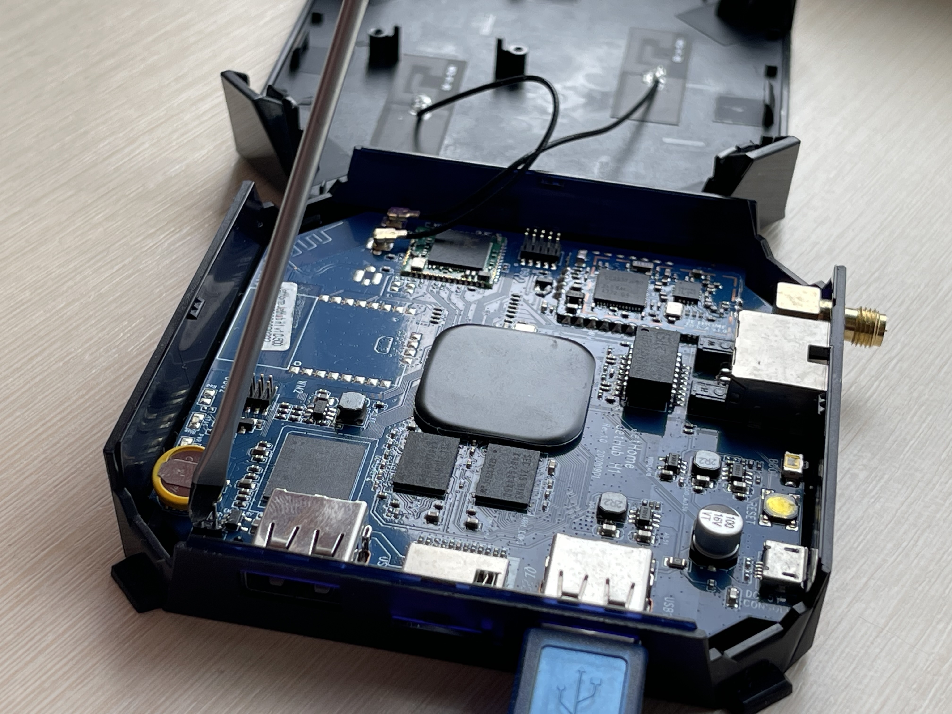
The figure shows:
ETHERNET- Ethernet connector.
DC 5V/CONSOLE- MicroUSB connector for controller power and Linux console output.
USB 1- USB connector for connecting external devices and controller firmware.
USB 2- USB connector for connecting external devices.
SD-CARD- slot for connecting MicroSD memory cards.
WIFI- Wi-Fi/Bluetooth module.
WM 1- The main module for communication with wireless devices (Zigbee).
WM 2- Additional module for communication with wireless devices (optional).
DBG 1- connector for updating the firmware of the main wireless module.
DBG 2- connector for updating the firmware of the optional wireless module.
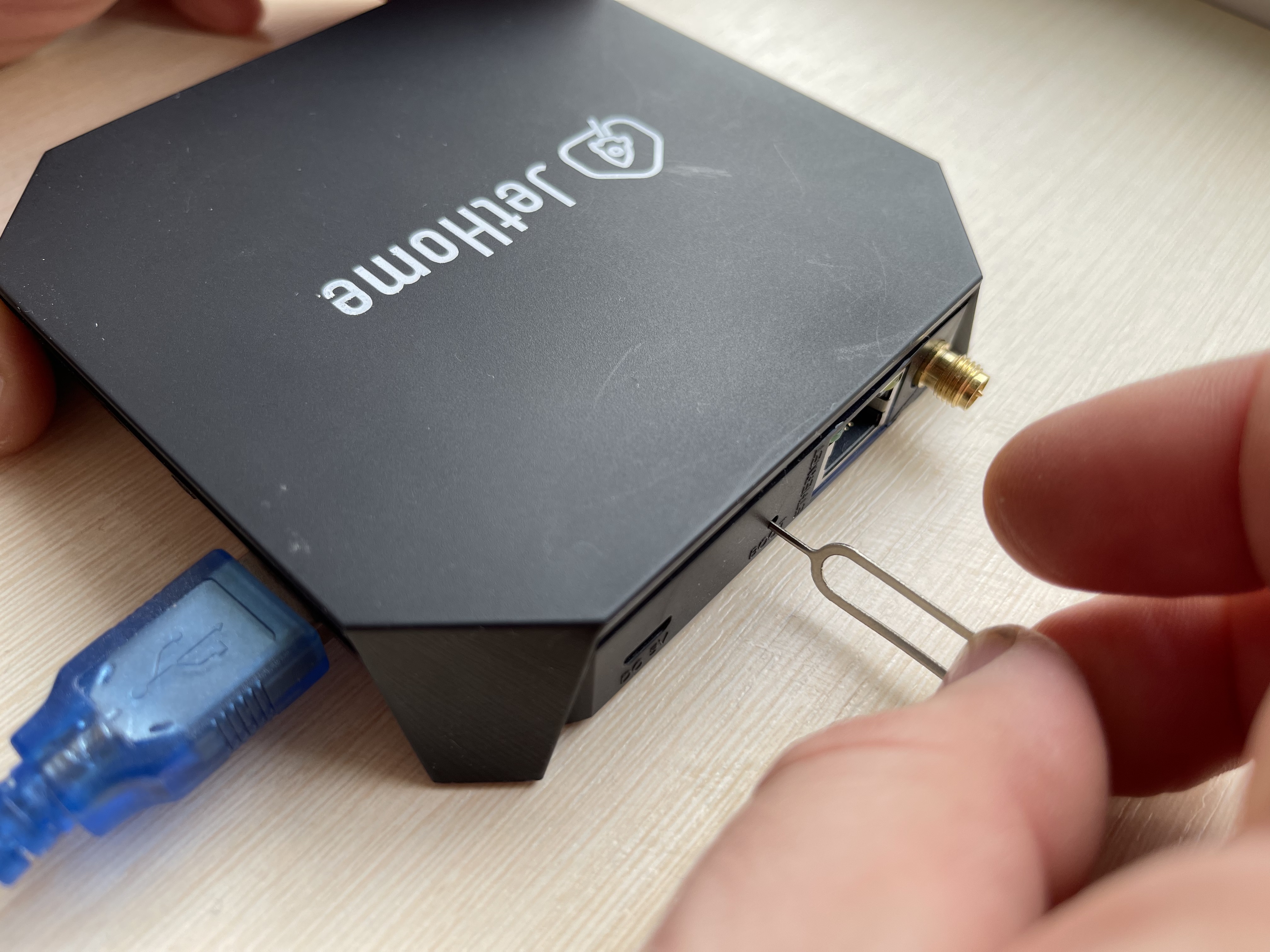
BOOT- button to switch the loading mode. The button is accessible through a hole in the controller housing. Do not use sharp objects or force when pressing the button.
RESET- controller hardware reset button.
UPDATE- pins to disable the built-in eMMC flash memory (used when restoring the controller firmware).
PWR- green LED indicating the presence of power.
STAT- blue custom LED.
Dimensions and weight
Overall dimensions: 100 x 97 x 20 mm;
Weight without power supply: 120 g
Communications
Integrated dual-band (2.4 GHz and 5 GHz) wireless module Wi-Fi/Bluetooth Realtek RTL8822CS. Supports Wi-Fi IEEE 802.11a/b/g/n/ac, 2×2 MIMO, and Bluetooth 5.0 standards.
Ethernet IEEE 802.3 10/100 Mbps.
Wireless Zigbee module TI CC2538 + CC2592 or TI CC2652P1 with up to 20 dBm output power and support for Zigbee 3 standard.
Interfaces
Supports MicroSD 2.x/3.x/4.x DS/HS cards;
2 x USB 2.0 high-speed;
The Serial Console is connected to the MicroUSB power connector.
LEDs
See also
There are two LEDs on the controller board:
LED |
Output |
Linux1 |
gpiolib |
Active low |
|---|---|---|---|---|
Blue |
GPIODV_24 |
596 (585) |
26 |
1 |
Green |
Power supply indication |
- 1
The values in brackets are for Linux Kernel, versions less than 6.2
Wireless module (Zigbee)
The controller motherboard has a mounting location for the wireless module. Depending on the controller configuration, a wireless module can be installed on the board (see Zigbee modules PCBA).
There is a WM DBG connector on the controller motherboard next to the wireless module seat for debugging or flashing the wireless module:
JTAG (WM DBG):

The module is connected to the UARTAO_B port of the processor, hardware control of reception/transmission (RTS and CTS lines) is not used. The device is displayed in the system as /dev/ttyAML2.
The GPIOs of the processor are used to control the wireless module, which are connected to the lines RESET and BOOT of the wireless module (see Working with discrete outputs in Linux)
Module output |
CPU output |
Linux sysfs2 |
Linux gpiolib |
Active low |
|---|---|---|---|---|
RESET |
GPIOAO_6 |
518 (507) |
gpiochip 0, line 6 |
0 |
BOOT |
GPIOAO_9 |
521 (510) |
gpiochip 0, line 9 |
1 |
- 2
The values in brackets are for Linux Kernel, versions less than 6.2
Hardware reset of the wireless module is done by writing a logic level 1 to GPIO RESET of the processor (see table above). Return to operation mode is performed by writing logical level 0 to GPIO RESET of the processor.
The boot mode is controlled by writing 0 or 1 to GPIO of BOOT processor (see table above). For the Zigbee wireless module, entering boot mode is done by logical level 0 on pin BOOT during Zigbee module reset.
Switching of modes takes place when the module is switched on or when it is reset by hardware reset. Therefore, after changing the logic level on the pin BOOT of the module, it is necessary to perform a hardware reset of the module.
Sample script to put Zigbee module into bootloader and firmware mode:
#!/bin/bash

# Specify path to flash tool
FLASH_TOOL=/path/to/tool
OPTIONS="--example options"
FIRMWARE=/path/to/firmware

# Put module into bootloader mode
echo "${0}: Invoke Zigbee module bootloader ..."
echo 0 > /sys/class/gpio/gpio521/value

echo "${0}: Reset Zigbee module ..."
echo 1 > /sys/class/gpio/gpio518/value
sleep 1
echo 0 > /sys/class/gpio/gpio518/value

echo "${0}: Flash Zigbee module ..."
${FLASH_TOOL} ${OPTIONS} ${FIRMWARE}

# Reset and put module into normal mode

# Pull up module BOOT line
echo 1 > /sys/class/gpio/gpio521/value

echo "${0}: Reset Zigbee module ..."
echo 1 > /sys/class/gpio/gpio518/value
sleep 1
echo 0 > /sys/class/gpio/gpio518/value
Console
The console is connected to the Micro-USB connector (also used to power the controller) via a Silicon Labs CP2102 USB-UART interface converter installed on the board.
The console is connected to the UART_AO_A port of the Amlogic S905W processor.
Hint
The driver for the USB-UART interface converter CP2102 for Windows OS can be downloaded at the manufacturer’s website.
In Linux it is usually not necessary to install an additional driver.
Port configuration:
Speed 115200 bps
Data length 8 bits
Stop bit 1
Parity is not used
Hardware flow control is not used
Power
The controller is powered from a stabilized DC source +5V, via a MicroUSB connector. Power consumption - not more than 5W (excluding external consumers connected to USB ports).
It is recommended to use the power supply unit supplied with the controller to power the controller.
Note
When powering the controller from a computer or other USB device, or when using a third-party power supply, make sure that the device or power supply is capable of providing the necessary output power:
Up to 5W if no additional devices will be connected to the controller.
Up to 10W if additional devices powered from the USB port will be connected to the controller’s USB ports.
Warning
When powering the controller from the USB port of a computer, be aware that the standard USB 2.0 interface may limit the output current to 0.5A, which may not be enough for normal operation of the controller under load.
Software
Officially supported software:
See also
Note
It is also possible to install such popular automation systems: OpenHAB, NodeRed and other Linux-based systems.
Controller firmware
Hint
You can find the current firmware image for your device here: JetHome firmware portal.
Switching to firmware mode

Disconnect the controller power supply (MicroUSB connector on the back of the case). Further in the process of flashing it is not necessary to connect it.
Open the case of the controller to get access to the board.
Connect the pins
Updatelocated on the controller board near the battery.Connect the controller with the cable USB A - USB A to the computer.
Make sure that the Burning Tool program has detected a connection to the controller.
Open the pins at
Update(Important!).Then start the process of flashing the controller.
The following steps of the flashing process are described at Amlogic Burning Tool.
Firmware
Recommended flashing methods:
Flashing from Windows is done using Amlogic Burning Tool.
Flashing from Linux is done using Khadas Utils.
Button BOOT

On the back side of the controller, between the Ethernet and microUSB interfaces, there is a BOOT button recessed into the case. The button allows you to change the boot order from eMMC to microSD card or implement a software response to a press. Some users pull the button off the board with excessive force or cause mechanical damage to it. Thereby rendering it unusable.
Safety precautions
Do not allow moisture to get on the contacts of output connectors and internal elements of the controller.
The controller must not be used in the presence of acids, alkalis, oils and other aggressive substances in the atmosphere.
The controller is not intended for use on objects that are potentially dangerous to life and health of others.
It is not allowed to connect the instrument to the local Ethernet network with access to the Internet network without providing reliable means of interconnection protection.
Operating conditions
Ambient temperature: 0..+40 С.
Relative humidity up to 80% without condensation.
Closed explosion-proof rooms without aggressive vapors and gases.
Wiring recommendations
It is recommended that stranded copper cables be used to ensure reliable electrical connections. The cable ends should be stripped and then tinned or cable lugs should be used. The cable strands should be stripped so that their bare ends do not protrude beyond the terminal block after connection to the controller.
General requirements for connection lines:
When laying the cables, the communication lines that connect the device to the sensors or other devices should be separated into separate routes, and located separately from power cables and cables that cause high-frequency and pulse interference.
To protect the inputs of the device from the influence of electromagnetic interference, the communication lines of the controller should be shielded. Special cables with braided shielding can be used as shields.
It is recommended to install line noise filters in the power line of the controller.
In the case of controlling power equipment, it is recommended that spark-quenching filters be installed on the switching line of this equipment.
Limitations
Warning
The controller is not designed for heavy 24/7 tasks such as video processing.