Linux controller JetHome JetHub D1+
Hint
The controller can be purchased from the manufacturer’s website: http://jethome.com/d1p/
General Description
Controller JetHome JetHub D1+ is designed to build home automation and monitoring systems: interrogating sensors, using as a data acquisition and transmission device, acting as a PLC in “smart home” systems, direct load control.
JetHome JetHub D1+ can be used as a central controller in a smart home together with wireless (Wi-Fi, ZigBee) and wired (RS-485) devices of other manufacturers.
The DIN-rail enclosure design allows the controller to be conveniently placed in the electrical panel of the house.
Features
Quad-core processor Amlogic A113X (ARM Cortex-A53) with operating frequency up to 1.4 GHz.
1GBytes or 2GBytes DDR4 RAM.
32GB non-volatile eMMC flash memory.
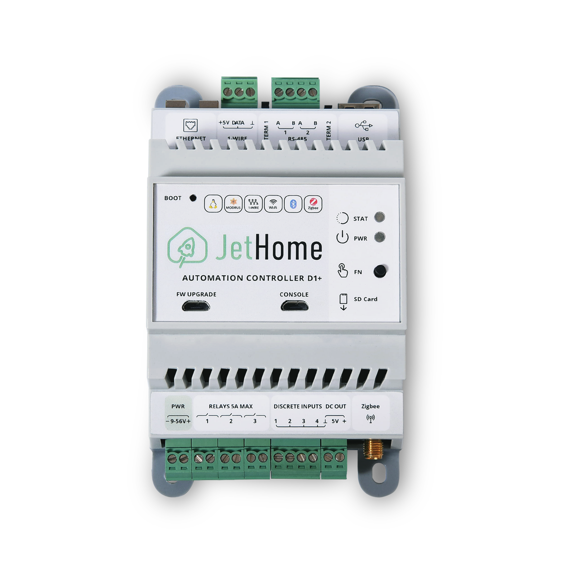
Design
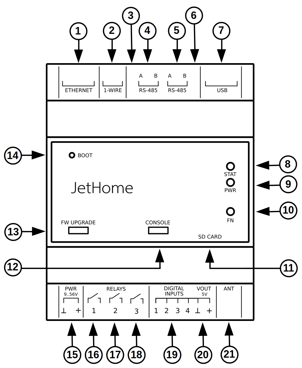
On the top side of the controller are:
Ethernet RJ45 connector
Connector 1-Wire
Port line terminator RS485-1
Port terminals RS485-1
Port terminals RS485-2
Port line terminator RS485-2
USB connector
On the front side of the controller there are:
Dual-color custom LED STAT
Power supply indication LED PWR
User button FN
MicroSD card slot
MicroUSB connector CONSOLE
MicroUSB connector FW UPGRADE
Internal boot mode switch button BOOT
On the underside of the controller are:
Power supply connection terminals
Relay 1 terminals
Relay 2 terminals
Relay 3 terminals
Binary input terminals
General contact terminal GND and power output 5V
Connector for external antenna of wireless communication module Zigbee
Dimensions and weight
Enclosure dimensions: 130 x 76 x 57 mm.
Enclosure width is 76mm, which is about 4.3 standard modules for a DIN rail (17.5mm).
Ability to mount the enclosure to a DIN rail 35mm.
Weight: 180 g
Equipment options
2 GBytes RAM, 32 GBytes eMMC, RTL8822CS (BT 5.0)
Revisions
Processor module revisions
v2.3
The WiFi module can be optionally replaced with the Amlogic W155S1 module
v2.2
Basic version of the processor module with Realtek RTL8822CS WiFi module
Motherboard revisions
v3.0
Galvanically isolated RS-485 ports and binary inputs
v2.1
The motherboard is optimized for the D1+ CPU module. The controller firmware update is now only available via a separate MicroUSB connector on the CPU module
v1.9
Two CP2104 USB-UART converter chips have been replaced with one CP2105 chip
v1.7
Software implementation of 1-Wire on GPIOs
v1.5
A 3-pin 3.5mm pitch connector is used for the 1-Wire bus connection
Interfaces
Wi-Fi/Bluetooth
Depending on the configuration, the controller can be equipped with one of two wireless communication modules:
Realtek RTL8822CS - Wi-Fi 2.4/5GHz, IEEE 802.11a/b/g/n/ac and Bluetooth 5.0
Amlogic AML W155S1 - Wi-Fi 2.4/5GHz, IEEE 802.11a/b/g/n/ac and Bluetooth 5.0
Warning
Simultaneous operation of the SD card and Wi-Fi module is not supported. Once the SD card is installed, the Wi-Fi module will be disabled.
Ethernet
The controller has one Ethernet 10/100 Mbit/s port and uses the IC-Plus IP101GR chip, which supports the IEEE 802.3/802.3u standards, as the physical layer Ethernet controller.
The Ethernet physical layer controller is installed on the processor module, the peripheral board has an Ethernet terminating transformer and an external RJ45 connector with indication of connection and Ethernet activity.
The following 40-pin connector pins are used to connect to the processor module: ETH_TXN, ETH_TXP, ETH_RXN, ETH_RXP, ETH_LED3, ETH_LED0
USB
There is one external USB 2.0 port on the controller’s motherboard for connecting peripheral devices.
The external USB port of the controller operates in USB host mode and is connected to the USB hub installed on the motherboard, to which the RS485 ports are also connected via a USB-to-UART port converter chip.
Note
The maximum current draw of a peripheral device connected to the external USB port of the controller should not exceed 0.5A. To protect the controller from exceeding the current consumption of an external device, a self-resetting fuse is installed in the USB power supply circuit to limit the current in the USB power supply circuit.
There is a separate external connector MicroUSB on the front panel for the firmware of the controller
Warning
Due to the USB current limit of 0.5A, it is prohibited to power the controller from an external MicroUSB port, except for its firmware. When connecting the controller via the MicroUSB firmware connector, the external USB 2.0 port on the motherboard as well as all internal controller peripherals connected to the USB port on the CPU will not be available.
MicroSD
The controller has a MicroSD connector for installing memory cards. The controller supports SD, SDHC and SDXC memory cards.
Warning
Simultaneous operation of the SD card and Wi-Fi module is not supported. Once the SD card is installed, the Wi-Fi module will be disabled.
Peripherals
LEDs
See also
There are two LEDs on the front panel of the controller: one to indicate the presence of supply voltage, the other is a custom two-color LED.
LED |
Output |
Linux1 |
gpiolib |
Active low |
|---|---|---|---|---|
Red |
GPIOA_0 |
538 (452) |
26 |
1 |
Green |
GPIOA_1 |
539 (453) |
27 |
1 |
- 1
The values in brackets are for Linux Kernel, versions less than 6.2
Discrete inputs
See also
The controller has 4 digital inputs for connection of “dry” contacts with shorting of the input to the common wire of the controller power supply (GND).
Maximum switching frequency of binary input state 400Hz.
Warning
The discrete inputs are not designed to be energized and may be damaged by voltages greater than 12V.
GPIO digital inputs table
Number |
Output |
Linux3 |
gpiolib |
Active low |
|---|---|---|---|---|
1 |
GPIOA_20 |
558 (472) |
46 |
0 |
2 |
GPIOA_19 |
557 (471) |
45 |
0 |
3 |
GPIOA_18 |
556 (470) |
44 |
0 |
4 |
GPIOA_17 |
555 (469) |
43 |
0 |
- 3
The values in brackets are for Linux Kernel, versions less than 6.2
Relay outputs
See also
The controller has 3 independent relay outputs with contact type NO contact.
Maximum switching AC current for resistive loads is 5A at voltages up to 250V. The mechanical life of the relay is 10,000,000 switching operations.
Warning
Do not exceed the maximum allowable current the relay can handle. The relay may be damaged if the current is exceeded!
GPIO relay outputs table
Number |
Output |
Linux4 |
gpiolib |
Active low |
|---|---|---|---|---|
1 |
GPIOA_4 |
542 (456) |
30 |
0 |
2 |
GPIOA_3 |
541 (455) |
29 |
0 |
3 |
GPIOA_2 |
540 (454) |
28 |
0 |
- 4
The values in brackets are for Linux Kernel, versions less than 6.2
1-Wire
Warning
Due to the peculiarity of the software implementation of 1 Wire in Linux the maximum number of devices on one bus is 5pcs.
1-Wire 3x3.5 mm connector
Pin assignment:
Number |
Destination |
Description |
|---|---|---|
1 |
+5V |
Power output +5V (for powering external devices 1-Wire) |
2 |
1-Wire Data |
1-Wire data bus |
3 |
GND |
Common 1-Wire |
RS-485 (Modbus)
See also
The controller has two RS-485 ports implemented with USB-UART Silicon Labs CP2104 or CP2105 interface converter chips depending on the revision of the motherboard. In the operating system these devices are displayed as /dev/ttyUSB0 and /dev/ttyUSB1.
Note
The ends of the RS-485 bus must be terminated with 120 Ohm resistors at both ends.
Note
To simplify installation, the controller has built-in terminators that connect to the RS-485 lines with jumpers located near the RS-485 terminals.
Real Time Clock (RTC)
See also
As a real time clock (RTC) is used the chip PCF8563, connected to the internal bus I2C of the processor module (bus I2C_B of the processor).
The RTC is powered by a 3V lithium battery of size CR1220 on the processor module.
Wireless module (Zigbee)
The controller motherboard has a mounting location for the wireless module. Depending on the controller configuration, a wireless module can be installed on the board (see Zigbee modules PCBA).
There is a WM DBG connector on the controller motherboard next to the wireless module slot for debugging or flashing the wireless module. The connector is installed depending on the configuration of the motherboard.
JTAG (WM DBG):

The module is connected to the UARTA0_B port of the processor, hardware control of reception/transmission (RTS and CTS lines) is not used. The device is displayed in the system as /dev/ttyAML2.
The GPIOs of the processor are used to control the wireless module, which are connected to the lines RESET and BOOT of the wireless module (see Working with discrete outputs in Linux):
Module output |
CPU output |
Linux5 |
gpiolib |
Active low |
|---|---|---|---|---|
RESET |
GPIOA_15 |
553 (467) |
41 |
0 |
BOOT |
GPIOA_10 |
548 (462) |
42 |
1 |
- 5
The values in brackets are for Linux Kernel, versions less than 6.2
Hardware reset of the wireless module is done by writing logic level 1 to GPIO RESET of the processor (see table above). Return to operation mode is performed by writing logical level 0 to GPIO RESET of the processor.
The boot mode is controlled by writing 0 or 1 to the GPIO BOOT of the processor (see table above). For the Zigbee wireless module, entering boot mode is done by writing a logic level 0 to the BOOT pin during a Zigbee module reset.
Switching of modes takes place when the module is switched on or when it is hardware reset. Therefore, after changing the logical level on the BOOT pin of the module, you must perform a hardware reset of the module.
Internal connectors
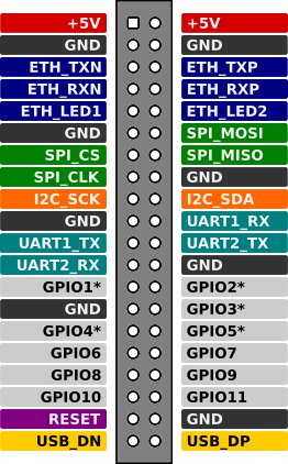
40-pin connector on the processor board
Signals output to the expansion connector
Ethernet (x4 PHY lines)
Ethernet LED (x2 lines)
USB (x2 lines)
SPI (x4 lines)
I2C (x2 lines)
x2 UART (x4 lines)
x11 GPIO
CPU RESET
+5В
Signal table
Output |
Destination |
Microprocessor output/peripherals |
Controller function |
|---|---|---|---|
1 |
+5.0V |
+5.0V |
|
2 |
+5.0V |
+5.0V |
|
3 |
GND |
GND |
|
4 |
GND |
GND |
|
5 |
ETH_TXN |
Ethernet |
|
6 |
ETH_TXP |
Ethernet |
|
7 |
ETH_RXN |
Ethernet |
|
8 |
ETH_RXP |
Ethernet |
|
9 |
ETH_LED3 |
Ethernet |
|
10 |
ETH_LED0 |
Ethernet |
|
11 |
GND |
GND |
|
12 |
SPI_MOSI |
GPIOX_17/SPI_MOSI_B |
|
13 |
GPIO0 |
GPIOX_16/SPI_SS0_B |
|
14 |
SPI_MISO |
GPIOX_18/SPI_MISO_B |
|
15 |
SPI_CLK |
GPIOX_19/SPI_CLK_B |
|
16 |
GND |
GND |
|
17 |
I2C_SCK |
GPIOAO_10/I2C_SCK_AO |
|
18 |
I2C_SDA |
GPIOAO_11/I2C_SDA_AO |
|
19 |
GND |
GND |
|
20 |
UART1_RX |
GPIOAO_1/UART_RX_AO_A |
Linux console RX |
21 |
UART1_TX |
GPIOAO_0/UART_TX_AO_A |
Linux console TX |
22 |
UART2_TX |
GPIOAO_4/UART_TX_AO_B |
|
23 |
UART2_RX |
GPIOAO_5/UART_RX_AO_B |
|
24 |
GND |
GND |
|
25 |
GPIO1 |
GPIOA_14 |
|
26 |
GPIO2 |
GPIOA_16 |
|
27 |
GND |
GND |
|
28 |
GPIO3 |
GPIOA_19 |
Discrete input 2 |
29 |
GPIO4 |
GPIOA_18 |
Discrete input 3 |
30 |
GPIO5 |
GPIOA_20 |
Discrete input 1 |
31 |
GPIO6 |
GPIOA_15 |
Zigbee module reset |
32 |
GPIO7 |
GPIOA_17 |
Discrete input 4 |
33 |
GPIO8 |
GPIOA_3 |
Relay 2 |
34 |
GPIO9 |
GPIOA_4 |
Relay 1 |
35 |
GPIO10 |
GPIOA_10 |
Zigbee module boot |
36 |
GPIO11 |
GPIOA_2 |
Relay 3 |
37 |
CPU_RESET |
||
38 |
GND |
GND |
|
39 |
USB_DN |
USB_DN |
USB data - |
40 |
USB_DP |
USB_DP |
USB data + |
Pinout
40-pin connector on the motherboard
Todo
Add a description of the pins
Console
The UART console is connected to the MicroUSB connector CONSOLE located on the front panel of the controller.
Hint
The driver for the USB-UART interface converter CP2102 for Windows OS can be downloaded at the manufacturer’s website.
In Linux it is usually not necessary to install an additional driver.
Port configuration:
Speed 115200 bps
Data length 8 bits
Stop bit 1
Parity is not used
Hardware flow control is not used
Power
Power options
The following power supply options are available:
From an external stabilized DC source via an external terminal.
Note
Recommended (rated) input voltage range 12V to 48V
The maximum input supply voltage range is 9 to 56V.
A stabilized DC power supply of at least 10W must be used.
Via technology Passive PoE via the Ethernet port connector.
Note
The recommended nominal input supply voltage Passive PoE is 12 to 48V.
The polarity of the connection does not matter.
The controller can power external low-power devices (sensors) with 5V supply voltage. The 5V output is connected to the terminal of the controller. The maximum current output to external load is 0.2A.
Warning
During flashing the controller can be powered from the MicroUSB port FW UPGRADE, but this method of power supply is not intended for normal operation of the controller.
When flashing the controller, disconnect all external loads from the controller. The total current consumption when powered from the MicroUSB port should not exceed 0.5A.
This power option is only for firmware mode, normal operation of the controller when powered through the USB) port is not possible and could cause the controller to malfunction.
When powered by USB, the RS485 ports on the motherboard will not be available.
Energy consumption
Power consumption of the controller itself is not more than 5W (excluding external consumers connected to the USB port and 5V output voltage terminal).
The power consumption depends on the load of the processor and controller peripherals.
Approximate current consumption from 24V DC power supply for controller with 1GB RAM/32GB eMMC configuration without CPU load is 0.06A, with 100% load of all 4 cores - 0.12A.
Software
Officially supported software:
See also
Note
It is also possible to install such popular automation systems: OpenHAB, NodeRed and other Linux-based systems.
Controller firmware
Hint
You can find the current firmware image for your device here: JetHome firmware portal.
Hint
Prepare a USB to MicroUSB cable.
Use the microUSB connector marked
FW UPGRADEon the front panel of the controller for flashing.
Switching to firmware mode
Warning
Before flashing:
Turn off the external power to the controller.
If using Passive PoE, disconnect the Ethernet connector.
Disconnect any devices that can draw power from the controller (USB, 1-Wire, etc.).
Switching to Firmware Mode:
Disconnect the controller from all power sources.
Press and hold the BOOT button on the controller front panel (the button is accessible through the hole on the controller front panel)
While holding down the BOOT button, connect the controller with the cable to the computer.
After connecting the cable, after 3-5 seconds the BOOT button can be released.
Firmware
Warning
Flashing using a method other than the recommended one may result in inoperability of the controller!
When flashing via microSD or USB Flash boot using the armbian-install utility or direct writing to eMMC, the service area which contains usid (including hardware version), based on which the firmware identifies the installed Wi-Fi / Bluetooth chip, will be erased.
Recommended flashing methods:
Flashing from Windows is done using Amlogic Burning Tool.
Flashing from Linux is done using Khadas Utils.
Possible problems during flashing
The program does not detect the connected controller
Hint
Make sure that the BOOT button is pressed while the USB cable is connected. It is not recommended to use sharp objects (needles, etc.), use blunt objects (paper clips, etc.)
Connect the USB cable quickly and fully. The USB connector is designed so that when the cable is connected, the power pins are connected first, then the data pins. This can result in a situation where the boot process has already begun when the power is applied, but the USB data lines have not yet been connected.
Use a USB 2.0 cable instead of a USB 3.0 cable
Safety precautions
During operation and maintenance of the controller the requirements of GOST 12.3.019-80, “The rules of operation of electrical installations of consumers” and “Safety rules for the operation of electrical installations of consumers” should be observed.
Any connections to the unit and maintenance work should be performed only when the controller and the actuators connected to it are de-energized.
Only qualified service personnel should be allowed physical access to the controller during installation and maintenance.
Do not allow moisture to get on the contacts of output connectors and internal elements of the controller.
The controller must not be used in the presence of acids, alkalis, oils and other aggressive substances in the atmosphere.
The controller is not intended for use on objects that are potentially dangerous to life and health of others.
It is not allowed to connect the instrument to the local Ethernet network with access to the Internet network without providing reliable means of interconnection protection.
Mounting
The unit can be installed in an electrical equipment cabinet or other location, where it must be protected from moisture, dirt and foreign objects, as well as vibration-free.
Note
For better cooling of the internal components, the housing should be installed in an upright position.
To install it, you have to:
Make sure there is enough space to connect the device and run the wires.
Securely fasten the unit to the DIN rail or to a vertical surface with screws.
To remove it from the DIN-rail you should:
Insert the tip of a screwdriver into the latch eyelet.
Press the latch down.
Take the controller away from the DIN rail.
Operating conditions
Ambient temperature: 0..+40 С.
Relative humidity up to 80% without condensation.
Closed explosion-proof rooms without aggressive vapors and gases.
Wiring recommendations
It is recommended that stranded copper cables be used to ensure reliable electrical connections. The cable ends should be stripped and then tinned or cable lugs should be used. The cable strands should be stripped so that their bare ends do not protrude beyond the terminal block after connection to the controller.
General requirements for connection lines:
When laying the cables, the communication lines that connect the device to the sensors or other devices should be separated into separate routes, and located separately from power cables and cables that cause high-frequency and pulse interference.
To protect the inputs of the device from the influence of electromagnetic interference, the communication lines of the controller should be shielded. Special cables with braided shielding can be used as shields.
It is recommended to install line noise filters in the power line of the controller.
In the case of controlling power equipment, it is recommended that spark-quenching filters be installed on the switching line of this equipment.
Limitations
Warning
The controller is not designed for heavy 24/7 tasks such as video processing.
Warning
Simultaneous operation of the SD card and Wi-Fi module is not supported. Once the SD card is installed, the Wi-Fi module will be disabled.